Series Circuits and Voltage Divider
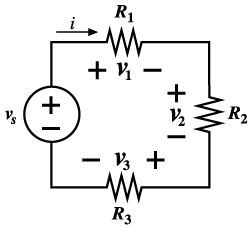
Figure
9.3 shows a series connection of three resistances
and a voltage source

Figure 9.3 Series
Circuit for a voltage divider.
Voltage Dividers
The method of voltage dividers requires
the engineer to anticipate the direction
of the physical current (current will be
positive out of the + terminal of the voltage
source). Applying KVL
We observe that the voltage
of the source divides between v1,
v2,
and v3.
We introduce Ohm’s law for each element
of the circuit
Where RT
is an equivalent resistance as shown in
Figure 9.3.
One common use for series circuits
is the construction of voltage dividers.
A voltage divider works
on the principle that the sum of the voltage
drops across a series circuit must equal
the applied voltage. Voltage dividers may
be constructed to produce any voltage desired.
The voltage across each resistance may be
found by using Ohm’s law applied to
the circuit in Figure 9.1.
We may summarize the above results by the
statement:
Of the total voltage, the fraction
that appears across a given resistance in
a series circuit is the ratio of the given
resistance to the total series resistance.
This is known as the voltage-division
principle.
Rules for Series Circuits:
-
The current is the same across any
point in a series circuit.
-
The total resistance is the sum
of each individual resistor.
-
The source voltage is equal to the
sum of the voltage drops across each
individual components.
|