Current Flow in a Capacitor
Consider a series circuit
containing a voltage source
v,
a switch, a resistor R,
and a capacitor C.
This is called a series RC
circuit.
The moment the
switch is closed:
-
There will be no charge on the plates
of the capacitor and therefore, no
voltage across the plates of the capacitor.
-
At the mall the source voltage appears
across the resistor. This means that
there is a current flow equal to v/R.
As the current flows, electrons build
up on one plate and holes with positive
charge on the other plate.
-
An electric field (E)
will build up between the plates as
the charges accumulate on the plates.
In the circuit shown in
Figure 12.2, the top plate
of the capacitor would be positively charged
and its bottom plate negatively charged
since the plates are arbitrarily assigned
as +
and -
according to their proximity to the nearest
voltage source terminal.
The electric field E
intimates a voltage across the plates of
the capacitor. As the voltage across the
capacitor increases, the voltage across
the resistor decreases reducing the current
flow. Eventually, the capacitor is completely
charged up and no more current will flow.
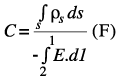
The capacitance of a two-conductor capacitor
is defined as
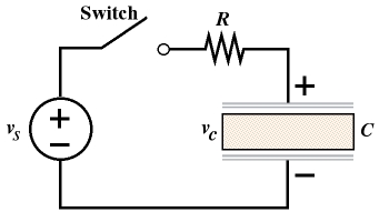
Figure 12.2 Series RC Circuit.
The charge q
is equal to the integral of the surface
charge density
 s
over surface S s
over surface S
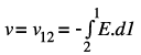
The voltage v
is related to E
by the following equation
Substituting into the equation of the capacitance
Where l
is the integration path from conductor 2
to conductor 1.
|